Motor Starter Switch Single Phase
A motor starter is made of two main components that work together to control & protect the motor; Single phase tiny motor starter.

Unique Wiring Diagram for Single Phase Dol Starter Well
Wiring diagram single motor with start stop switch single phase motor wiring with contactor diagram electrical 44 luxury single phase submersible pump starter wiring aim manual page 54 single phase motors and controls starters the many types of electric starters star delta starter single line diagram pdf delta starter

Motor starter switch single phase. This motor is widely used in ceiling fans due to various advantages over other types of motors. Soft start of induction motor by acpwm in this drive, the load is connected in series with the input terminals of the bridge rectifier and its output terminals are connected to the pwm controlled power mosfet (igbt or bipolar or power transistor). Single phase dol starter wiring diagram.
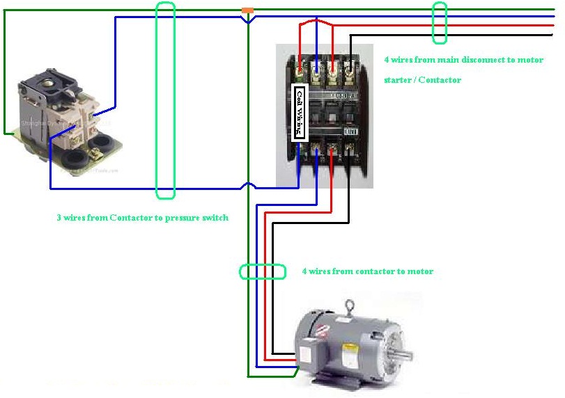
For magnetic starters, a pushbutton or a selector switch connected to a plc digital input is used to activate a plc digital output.the plc output will pull in a coil that magnetically holds the starter contacts closed, allowing current to pass to the motor. The above diagram is a complete method of single phase motor wiring with circuit breaker and contactor. The motors wiring diagram on the underside of the junction box is badly faded part of it reads t1 t2 are the at leads.
In order to keep a minimum and flexible stock, the thermal overload relay must be ordered separately related to the actual full load current of motor. In case of 120v single phase dol motor control 1how neutral should be wired should it be wired through overload relay or not. The purpose of the contactor is to switch on/off the power supply to the motor by making or breaking the contact terminals.
Can someone please explain or even better sketch out where the wires need to go, i have a fair idea already just want some good advice before i continue. The purpose of this circuit is to protect the motor from potential harm. Enclosure size is 8″ x 6″ x 3.
Compact design screw or din rail mounting standard breaking capacity thermal and electromagnetic trip rated operational current up to 25a switching capacity 150/50ka/145v In the above one phase motor wiring i first connect a 2 pole circuit breaker and after that i connect the supply to motor starter and then i do cont actor coil wiring with normally close push button switch and normally open push button switch and in last i do connection between capacitor. Hi, hoping you all can help me wire up my single phase 240v induction motor.
The single phase motor are those motor which is working one phase and neutral (ground) supply for doing his duty and a 3 phase motor required 3 phase power source. And the normally open and normally close push button shown. The overload relay is designed so the current to the motor is shared between phases, so if you only wire up one phase, then all the motor current goes through one of the contacts on the overload, and you can.
Once the motor starts a rotor mounted centrifugal switch disconnects the start winding and the motor continues to run on the main winding. Previously, we discussed what a magnetic motor starter is (a contactor and an overload relay). Katariya 1.5amps to 32 amps single phase dol motor starter, voltage:
Typical applications for these combinations include smaller crimping machines, grinders, drill presses, and all types of saws. Single phase motor overload protection. We are manufacturer of single phase capacitor box/motor starter ,welcome you contact with us ,any reqruirement ,pls feel free to contact us and we can give you detailed reply on the first time.

Direct Online Starter Animation Diagrams Diagram

Wiring Diagram For 220 Volt Air Compressor, http

Electric Motor Starter Control 5 Hp Single Phase

Submersible Motor Starter wiring Single Phase

Three Phase DOL Starter Wiring Diagram With MCCB Contactor

Three Phase Dol Starter Wiring Diagram Component Single

Motor Forward Reverse Wiring Diagram Elec Eng World

Submersible Pump Control Box Wiring Diagram For 3 Wire

Wiring Diagram Motor Fresh Single Phase Motor Starter

3 wire submersible well wiring diagram get free Circuit

Single Phase Submersible Pump Starter Wiring Diagram

Great Single Phase Starter Wiring Diagram A Big Compressor

Single Phase Reversing Contactor Wiring Diagram Reversing
Three+Phase+Contactor+Wiring+Diagram..JPG (811×572

Phase Controller Wiring / Phase Failure Relay Diagram

Rated characteristics of Electrical Contactors Electro

Single Phase Motor Starter Wiring Diagram Submersible Well

Single Phase Motor Wiring With Contactor Diagram

stop start wiring diagram for air compressor with overload


No comments: